
 Español
  English
 Professional installation of KMEW facades
Manuals, fixing system, accessories and technical support to install Filltect and Ceradir V correctly.
See the assembly system
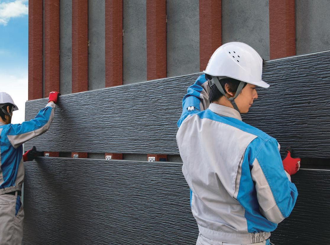
Assembly system
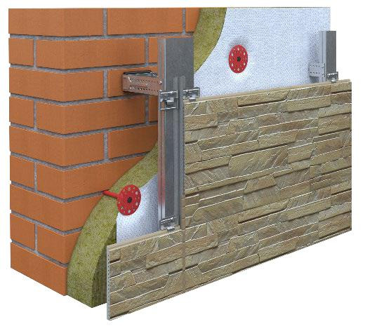
Substrate, subframe, ventilation cavity and panel work together. The sequence below is the order of work on site.
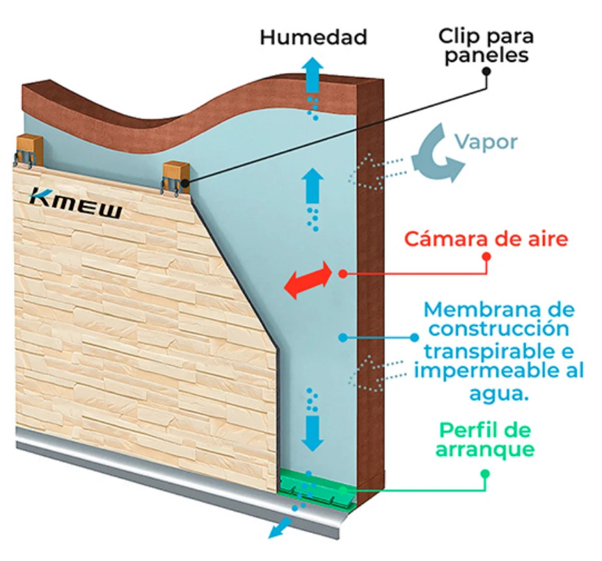
01
Substrate and subframe
Plumb · alignment · geometry
02
Setting out
Modulation · openings · corners
03
Starter
Starter profile · air inlet
04
Clips and panels
Installation sequence
05
Junctions and trims
Openings · corners · coping · base
06
Final check
Alignment · cleaning
Technical Documentation
Manual
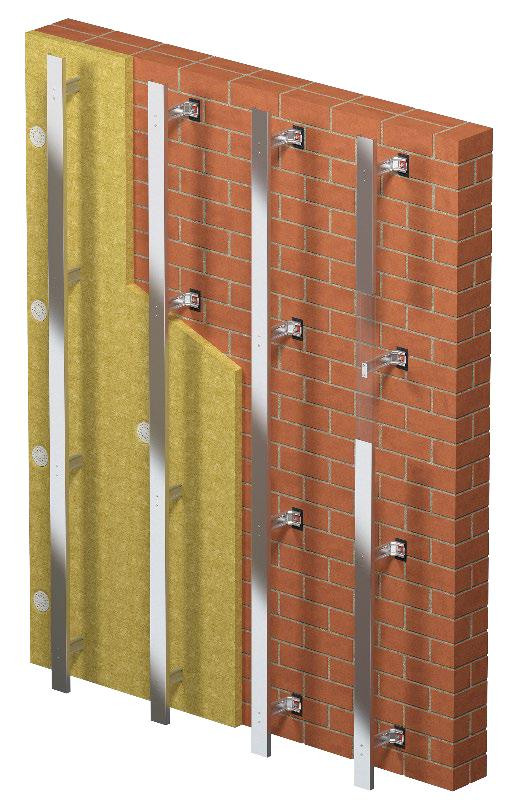
Aluminium subframe
Filltect / Ceradir V
Open
Manual
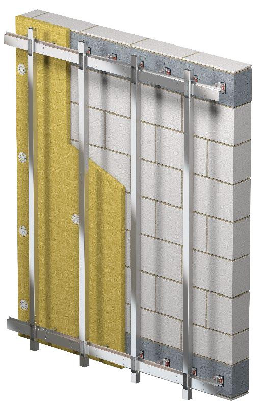
Steel subframe
Filltect / Ceradir V
Open
ETA
Filltect
European Technical Assessment
Consult
ETA
Ceradir V14
European Technical Assessment
Consult
EPD
Photocatalytic Filltect 16 mm
Environmental Product Declaration (EPD)
Consult
Details
Construction details
Depending on the series and installation orientation
Request
Installing Filltect and Ceradir V
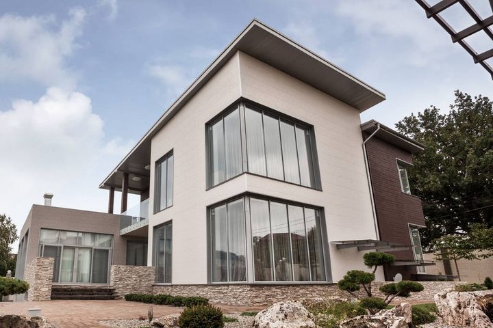
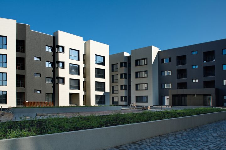
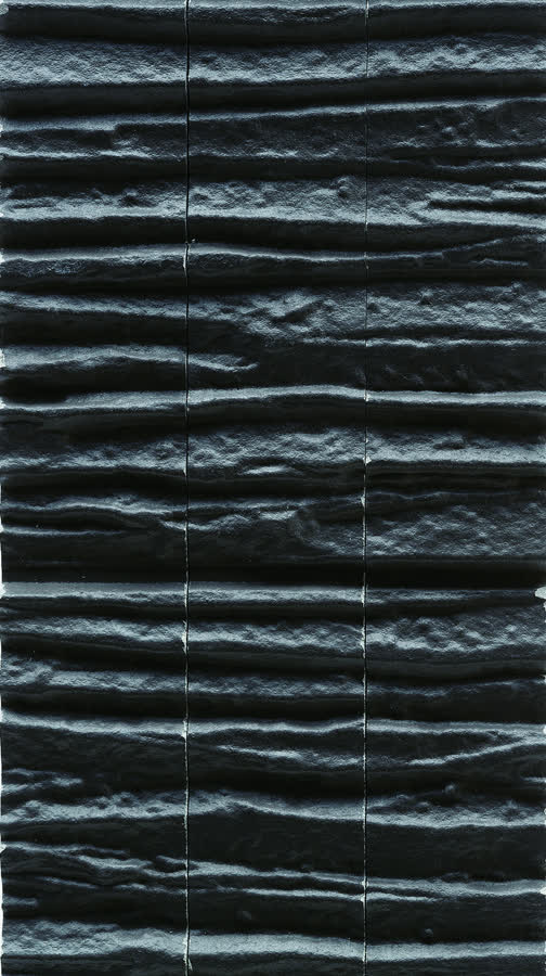
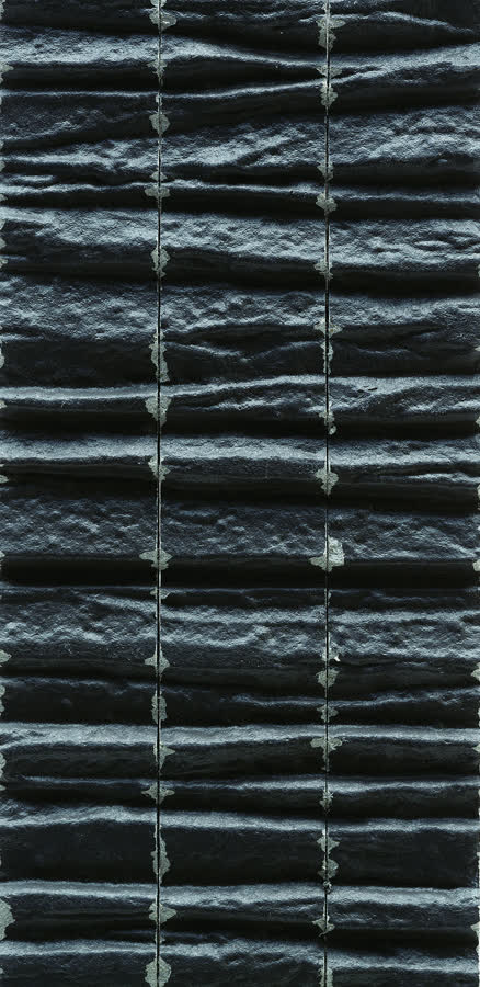
FILLTECT and CERADIR V are installed following the same logic and the same sequence of work. For the installer the process is practically the same; only certain clips, accessories and series-specific requirements change.
| FILLTECT | CERADIR V | |
|---|---|---|
| Main focus | Design and architectural expression | Height, light weight and refurbishment |
| Thickness | 16 mm | 14 mm |
| Format | 3030 × 455 mm | 3000 × 455 mm |
| Weight per m² | 18.12 kg/m² | 14.65 kg/m² |
| Surface technology | Photocatalytic ceramic coating | Hydrophilic coating |
System and accessories
Starter profile
First row
Fixing clip
Concealed fixing
Joiner
System joints
Trims
Corners and openings
Subframe
Aluminium / steel
Fasteners
According to the substrate, the subframe and the project calculation
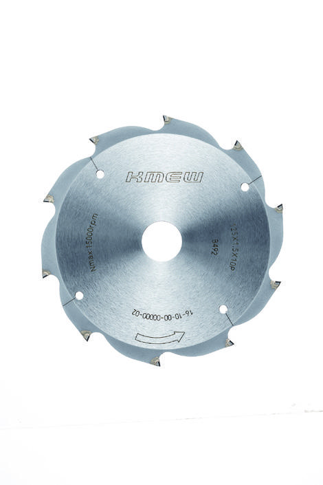
Cutting and preparation
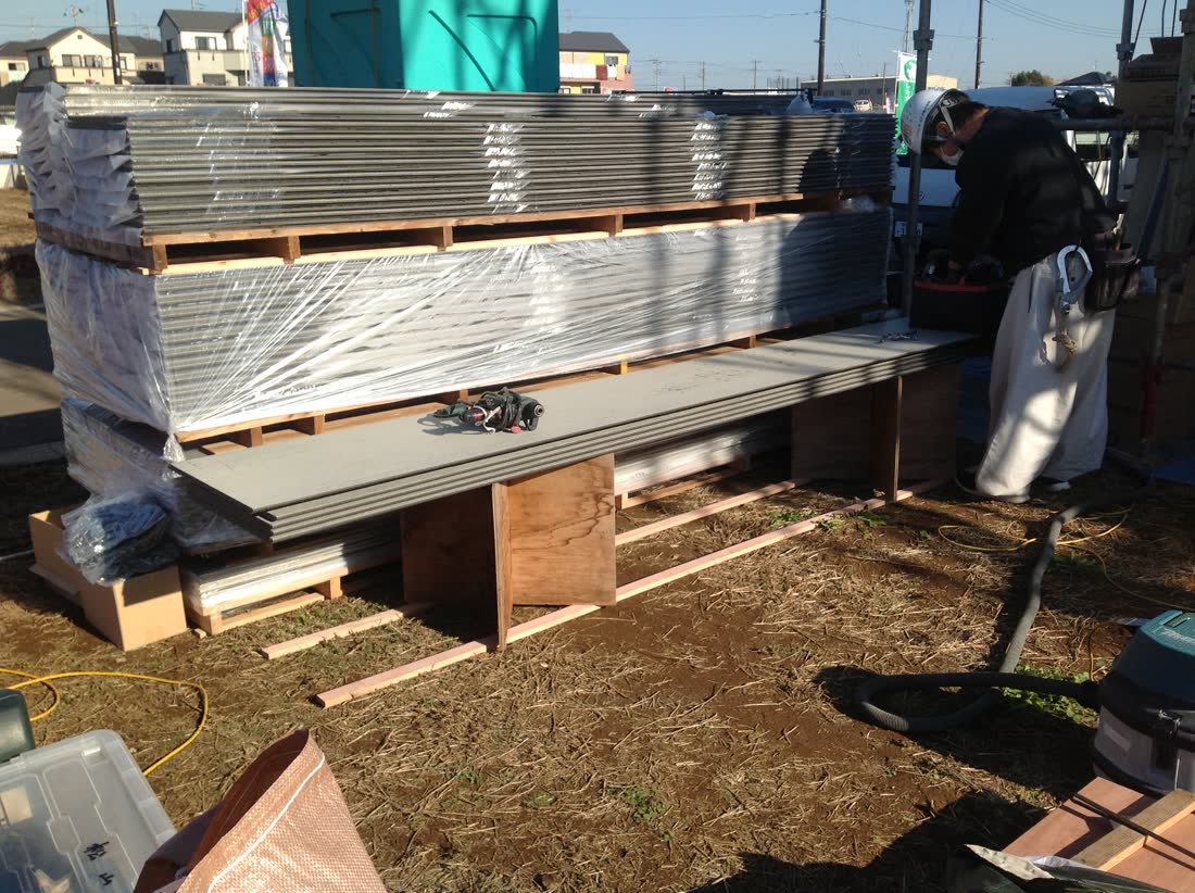
Panels are cut and adjusted on site when the setting out requires it. The general recommendations below apply to installation work; the specific dimensions, spacings and requirements are in the current manual.
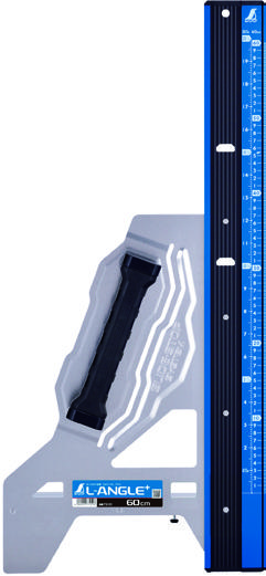
- Tools and cutting method as set out in the current manual
- Dust extraction and personal protective equipment
- Storage and handling of the panel on site
- Edge and trim treatment according to the series, the detail and the current manual
Junctions and details
Send us the construction detail, the panel series, the installation orientation and the type of subframe so that we can study the applicable solution.
Opening
Windows and doors
Request detail
Corner
Corners
Request detail
Coping
Coping
Request detail
Base
Starter and base
Request detail
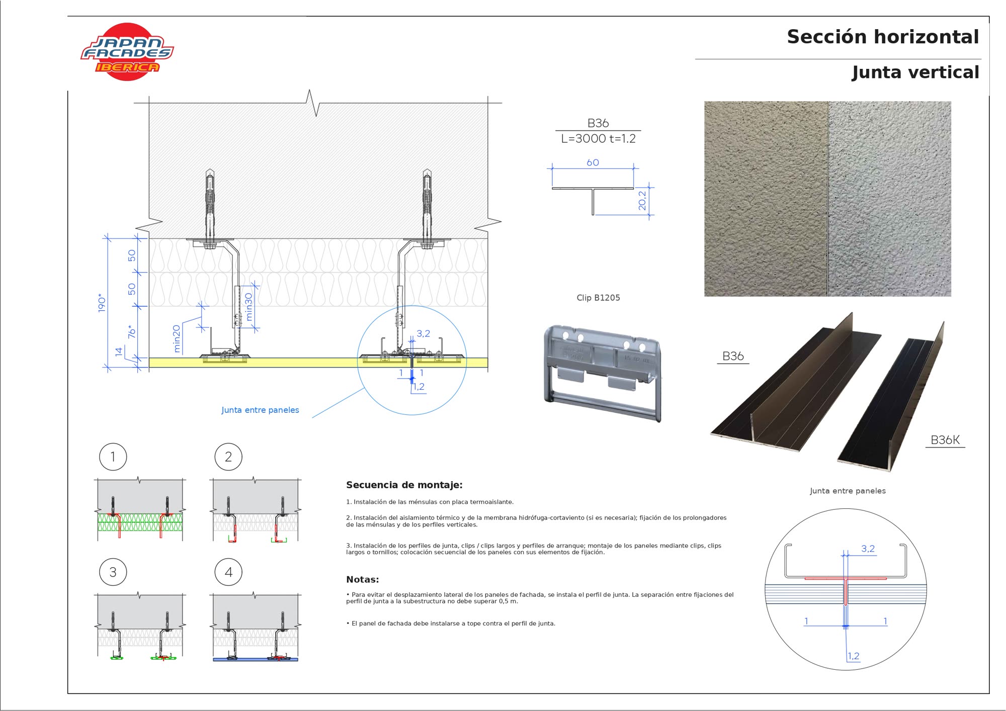
Example drawing
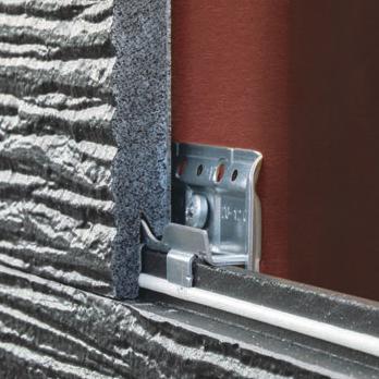
Mechanical fixing on site
- The panels are installed with mechanical fixing, with no setting times for render mortars.
- More predictable work sequence
- Installation with mechanical fixing, with no wet coatings applied to the panels.
- Panel + clip + subframe
- Less dependence on drying processes
Installation is still subject to safety, wind, heavy rain, ice, access and storage. The real advantage is that the cladding does not need to cure or dry wet layers before work can continue.
Installation procedure
Installation is organised in eight stages, from checking the subframe to final cleaning. Fixings, spacings and construction details must comply with the current manual for the series, subframe and installation orientation used.
01
Checking the subframe
Check the plumb, alignment and position of the subframe profiles. Verify the anchors and fixings in accordance with the project and the installation manual.
02
Defining the panel layout
Define the modulation, joints and make-up pieces before installation. Take openings and corners into account to reduce unnecessary cuts and keep a uniform layout.
03
Installing the starter flashing
Position and level the flashing at the base of the facade. Keep the specified clearances from the finished ground level and from the panels to allow drainage and ventilation.
04
Setting out
Mark the horizontal and vertical reference lines for the starting row and panel placement. Use them to keep panels, joints and trims aligned throughout installation.
05
Installing trim profiles
(external and internal corners, vertical joints, etc.)
Install the corner, joint and junction profiles before fitting the panels that depend on them. Select the pieces and their position according to the series and the construction detail.
06
Cutting and fitting the panels
Cut the panels with the tools specified in the manual, using dust extraction and suitable protective equipment. Observe the prescribed fixings and spacings, and treat the edges where the series requires it.
07
Touch-up painting and inspection
Inspect the surfaces and trims. Apply touch-up paint only where needed, using the product that matches the panel and following the manufacturer’s instructions.
08
Cleaning and waste management
Remove offcuts, dust and packaging waste. Clean the panels according to the manufacturer’s instructions and manage waste in line with site conditions.
Plan the work taking into account safety, weather conditions, access and panel storage.
Technical installation enquiry
If you have any doubts about a junction or a fixing, consult us before carrying out the detail.
Useful documentation for the enquiry:
- Photographs of the junction or detail
- Sketch, PDF or drawing
- Panel series and reference
- Type of subframe
- Short description of the enquiry
Privacy
The files are used solely to study the enquiry and prepare the technical and commercial response.
Privacy PolicySend technical enquiry